
MIPI Monitoring Board
SVM-06
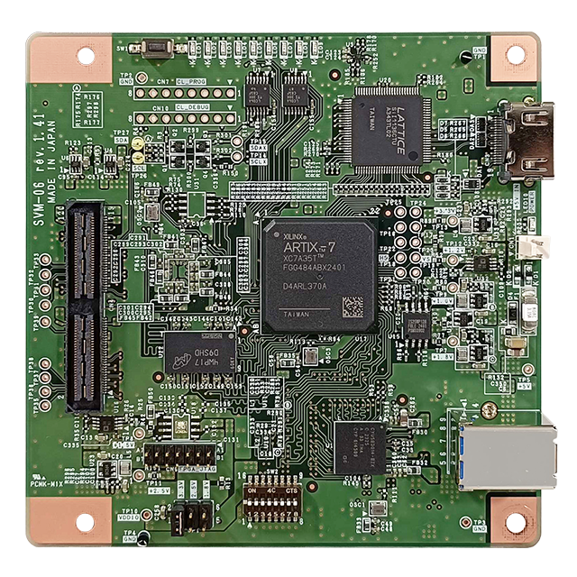
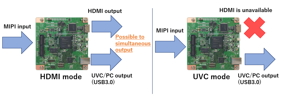
SVM-06 is a board for recording and displaying MIPI CSI-2 video signals. It can output to both HDMI and UVC (USB3.0/PC), providing the convenience of displaying images on a monitor while simultaneously capturing them on a PC.
The transfer rate is 1.5Gbps per MIPI lane, and it supports video output in 4K resolution.
It also has various functions: capturing Embedded Data and multiple Virtual Channels; simultaneously capturing videos from two image sensors and displaying them side by side; capturing videos from multiple cameras using this board for the number of cameras.
The capture function is compatible with Windows and Linux environments that support UVC.
Characteristics
- Supports MIPI CSI-2 1.5Gbps / lane
- Output to USB3.0 & HDMI simultaneously
- Compatible with 6Gbps automotive deserializer
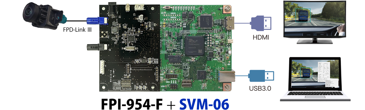
Configuration Example
Specification
| Item | Specification | Remarks | |
|---|---|---|---|
| Video Input Interface | MIPI D-PHY CSI-2 video signal | Supports Non-Continuous / Continuous Clock Standard specification : 4 data lanes + 1 clock lane With customization : Supports up to 8 data lanes + 2 clock lanes Supports either 2 inputs or 1 input + 1 output |
|
| Video Output Interface | UVC (USB Video Class) HDMI 1.4 |
ー | |
| Input Resolution | Max. 8190 x 4095 pixel | The supported input width depends on the number of lanes. | |
| Output Resolution | Max. 8190 x 4095 pixel (UVC mode) Within 3.0 Gbps (HDMI mode) Up to 3840 × 2160, 30fps |
Supported resolutions in HDMI mode: 1280x720/ 1920x1080/ 2560x1440/ 3840x2160 For UVC mode, the effective in‑frame data rate must be within 3.0 Gbps. |
|
| Sync Signal | Frame Start / Frame End | ー | |
| MIPI Data Lane | 1 ~ 4 lanes | ー | |
| Data Rate Per Lane | 20 ~ 1500 Mbps | ー | |
| Clock Rate | 10 ~ 750 MHz | ー | |
| Supported Pixel Format | YUV422 8bit / RGB24 / Raw8, 10, 12, 16, 20 |
ー | |
| Other Interface | I2C | 1 channel:SCL, Frequency 100 / 200 / 400 kHz | Voltage level follows VDDIO |
| GPIO | 16bit, IN / OUT direction control for each bit Direct connection to FPGA |
Voltage level follows VDDIO | |
| Power Supply | Input Power | USB bus power / Dedicated 2pin connector (5V) | ー |
| Output Power | VDDIO output (1.8V, 2.5V, 3.3V) 5V, 3.3V, 1.2V output |
Using the common internal power supply: 150mA (VDDIO 1.8V), 800mA (VDDIO 2.5V, 3.3V), 2A (5V via CN1), T.B.D. (1.2V) |
|
| Protection Device | Fuse 3.15 A | ー | |
| Other Function | Test pattern output Image clipping Automatic I2C transmission at startup (ROM boot) Virtual Channel, Embedded Line |
ー | |
| Interface Connector | 120 pin (QSH-060-01-L-D-A) | Compatible with the 60pin interface for our SVM‑MIPI board. | |
| FPGA | Artix-7 (XC7A35T) CrossLink (LIF-MD6000) |
ー | |
| Frame Memory | 256 MByte (DDR3-SDRAM) | ー | |
| USB | Device Controller | Infineon EZ-USB FX3 | ー |
| Connector | USB3.0 Type-B | ー | |
| HDMI Chip | Sil1136 | ー | |
| Dimensions | length x width x height = 101.6 x 101.6 x 25.7 (mm) |
Including spacer (10mm) in height. | |
| Software (Windows) | NVCap, SVMCtl, SVMUpdater | ー | |
| Supported Our Deserializer Board | FPI-954-F, GMI-9286-F, GMI-9288-F, GVI-4960-F, etc. |
ー | |
Documents
Design Documents
- SVM-06_Rev.1.3_Hardware Specification (PDF)
- SVM-06_Rev.1.4_Hardware Specification (PDF)
- SVMCtl Software Manual (PDF)
- NVCap Software Manual (PDF)
Full Package Download
MIPI Monitoring Board Evaluation Kit
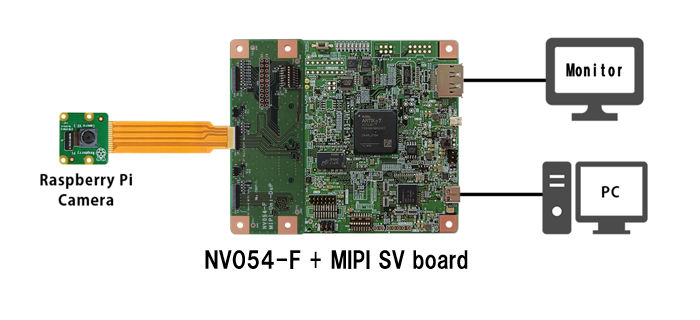
As shown in the image, it is possible to connect and use a Raspberry Pi Camera using the "NV054-F". We can also provide a configuration file for camera operation.
*Raspberry Pi camera and cable are not included.
Application
Display video signal of camera modules or CMOS sensors to DisplayPort monitor, Around view development, Simultaneous monitoring of multiple sensors.
Application Areas
Automotive / transportation equipment, medical testing / analysis / measurement, IT / information / communications, software, education / research institutions, and so on.